
WALFRONT ADF4351 RF Signal Generator Module
دليل تعليمات المستخدم
1. المقدمة
This manual provides detailed instructions for the proper use and operation of the WALFRONT ADF4351 RF Signal Generator Module. Designed for hobbyists and engineers, this frequency synthesizer offers a wide output frequency range and flexible control options. Please read this manual thoroughly before operating the device to ensure safe and efficient use.
2. معلومات السلامة
مهم: This board requires professional knowledge and ability for proper use. Incorrect handling or connections can lead to damage to the module or connected equipment. Always observe the following safety precautions:
- تأكد من حجم امدادات الطاقةtage is within the specified range (DC4-9V, typical 5V).
- Avoid short circuits on any pins or connectors.
- Do not expose the module to moisture, extreme temperatures, or static electricity.
- Handle the board by its edges to prevent damage to components.
- Disconnect power before making or changing any connections.
3. انتهى المنتجview
The WALFRONT ADF4351 module is a compact RF signal generator and frequency synthesizer. It features a well-designed circuit board layout and offers a versatile frequency range for various RF applications.
المميزات الرئيسية:
- Versatile Frequency Generation: Output frequency range from 35 MHz to 4.4 GHz.
- Easy Control Interface: Three-wire SPI design for straightforward operations and flexible frequency adjustments.
- Crystal Oscillator Included: Features a 25 MHz active crystal oscillator for reliable and accurate frequency synthesis.
- وظيفة كتم الصوت: RF output level can be muted via a dedicated pin or software control.
- تصميم مضغوط: Measures 49 x 37 x 12 mm, ideal for integration into custom setups and DIY projects.
مكونات الوحدة:
The module consists of the ADF4351 chip, a 25M active crystal oscillator, power input, control pins, and SMA output connectors.

الشكل 3.1: الأعلى والأسفل view of the WALFRONT ADF4351 RF Signal Generator Module. The top view shows the main components including the ADF4351 chip, crystal oscillator, and control pins. The bottom view shows solder pads and mounting holes.
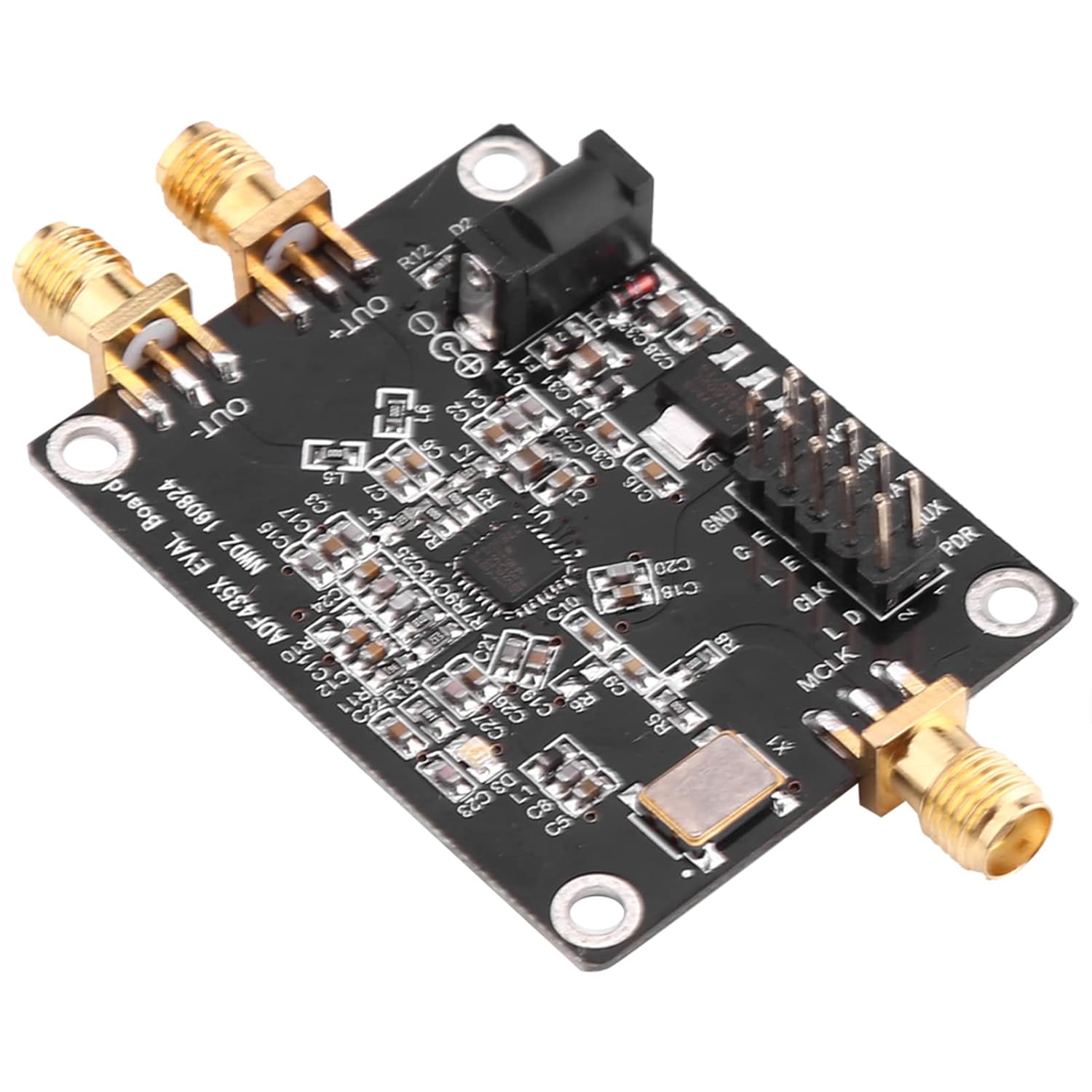
الشكل 3.2: بزاوية view of the ADF4351 module, highlighting the SMA output connectors and the DC power input jack.
4. الإعداد
Follow these steps to set up your ADF4351 module:
4.1. توصيل التيار الكهربائي
- Locate the DC002 interface on the module.
- Connect a stable DC power supply providing 4-9V (typical 5V) to this interface. Ensure correct polarity.
4.2. Signal Output Connection
- Identify the SMA female connectors labeled 'OUT+' and 'OUT-'.
- Connect your RF measurement equipment or load to these SMA connectors using appropriate RF cables.

الشكل 4.1: الصورة عن قرب view of the SMA female output connectors ('OUT+' and 'OUT-') on the ADF4351 module.
4.3. Control Interface Connection
The module is controlled via a three-wire SPI interface. All control pins are led out for convenient operation. Refer to the provided circuit diagram (in PDF format) for detailed pin assignments.
- Connect the SPI control pins (e.g., CLK, DAT, LE) from your microcontroller or control board to the corresponding pins on the ADF4351 module.
- ضمان المجلد المناسبtage levels (e.g., 3.3V) for the control signals.

الشكل 4.2: مفصل view of the control pin header (GND, 3V3, DAT, LE, CLK, MUX, PDR) and the DC power input jack.
5. تعليمات التشغيل
Once the module is powered and connected, you can begin operating it using the SPI interface.
5.1. Frequency Generation
The ADF4351 module can generate frequencies from 35 MHz to 4.4 GHz. The output signal type varies with frequency:
- 2.2 GHz - 4.4 GHz: Fundamental wave (sine wave).
- 35 MHz - 2.2 GHz: Fundamental division (square wave).
5.2. SPI Control
The three-wire SPI interface allows for comprehensive control over the module's functions. This includes:
- تعديل التردد: Program the desired output frequency.
- Point Frequency Sweep: Configure the module to sweep across a range of frequencies.
- القفز الترددي: Implement frequency hopping sequences.
- يخطو: Adjust frequency in precise 1 kHz steps.
The module can be controlled by official software provided by the manufacturer. Refer to the software documentation and the provided test program for programming examples and detailed SPI communication protocols.
5.3. Mute Functionality
The RF output level can be muted to optimize signal usage or for testing purposes. This can be achieved in two ways:
- Via Pin: Use a dedicated control pin (refer to circuit diagram for specific pin).
- عبر البرمجيات: Implement the mute function through SPI commands.
6. المواصفات
| المعلمة | قيمة |
|---|---|
| خرج نطاق الترددات | ADF4351: 35 MHz - 4.4 GHz |
| مزود الطاقة | DC002 Interface DC4-9V (typical 5V) |
| Output Signal (2.2-4.4 GHz) | Fundamental wave (sine wave) |
| Output Signal (35M-2.2 GHz) | Fundamental division (square wave) |
| موصل إخراج الإشارة | أنثى SMA |
| مذبذب بلوري | 25 MHz active crystal oscillator (+/-50ppm) |
| واجهة التحكم | Three-wire SPI |
| أبعاد | 49 × 37 × 12 ملم (1.93 × 1.45 × 0.47 بوصة) |
| وزن العنصر | 0.459 أونصات |
| رقم الموديل | WALFRONT0fyc712r5g |
7. الصيانة
The ADF4351 module is designed for durability, but proper care can extend its lifespan:
- حافظ على نظافة الوحدة وخلوها من الغبار والأوساخ. استخدم قطعة قماش ناعمة وجافة للتنظيف.
- قم بتخزين الوحدة في بيئة جافة، بعيدًا عن أشعة الشمس المباشرة ودرجات الحرارة القصوى.
- Avoid physical shock or excessive vibration.
- Ensure all connections are secure but do not overtighten SMA connectors.
8. استكشاف الأخطاء وإصلاحها
If you encounter issues with your ADF4351 module, consider the following common troubleshooting steps:
- لا يوجد طاقة: تحقق من توصيل مصدر الطاقة وتأكد من أن مستوى الصوتtage is within the 4-9V range. Verify the power adapter is functioning correctly.
- No RF Output:
- تأكد من أن الوحدة تتلقى الطاقة.
- Check if the RF output has been muted via pin or software.
- Ensure the SMA cables and connected equipment are working correctly.
- Incorrect Frequency Output:
- Double-check your SPI programming for the desired frequency.
- Ensure the SPI communication is stable and error-free.
- Verify the 25 MHz crystal oscillator is functioning.
- Module Not Responding to SPI:
- Check all SPI pin connections (CLK, DAT, LE) for continuity and correct wiring.
- Ensure the control signals are at the correct voltage levels (e.g., 3.3V).
- Review your SPI communication code for any errors.
If problems persist, and you have verified all connections and programming, it is recommended to consult the official circuit diagram and test program, or seek assistance from experienced professionals.
9. معلومات الضمان
Specific warranty details for the WALFRONT ADF4351 RF Signal Generator Module are typically provided by the seller or manufacturer at the time of purchase. Please retain your proof of purchase for any warranty claims. For detailed information regarding warranty coverage, duration, and terms, please contact your point of purchase or the Walfront customer support directly.
10. الدعم
For further technical assistance, documentation, or inquiries not covered in this manual, please contact Walfront customer support. You may also find additional resources, including circuit diagrams and test programs, on the manufacturer's official webالموقع أو من خلال قنوات دعم البائع.