1. المقدمة
Welcome to the user manual for the Machinist MR9A PRO MAX X99 Motherboard. This guide provides detailed instructions for installing, operating, maintaining, and troubleshooting your motherboard. Please read this manual thoroughly before beginning installation to ensure proper setup and optimal performance.
The Machinist MR9A PRO MAX X99 is designed to support LGA 2011-3 Intel Xeon E5 V3&V4 CPU Processors and DDR4 RAM Memory, offering robust performance for various computing needs.
2. انتهى المنتجview
2.1 الميزات الرئيسية
- LGA 2011-3 Socket for Intel Xeon E5 V3&V4 Processors
- DDR4 RAM Memory Support (Four Channel)
- NVME M.2 SSD Support
- USB 3.0 Connectivity
2.2 تصميم اللوحة الأم ومكوناتها
تعرّف على المكونات والموصلات المختلفة الموجودة على اللوحة الأم.

Figure 2.2.1: Detailed layout of the Machinist MR9A PRO MAX X99 Motherboard, highlighting key connectors such as CPU fan headers, power connectors (24PIN DC, 8PIN DC), DDR4 RAM slots, SATA ports, M.2 slots (SATA M.2, NVME M.2, WIFI M.2), USB 2.0 and 3.0 headers, PCIe slots, audio headers, and diagnostic card display.
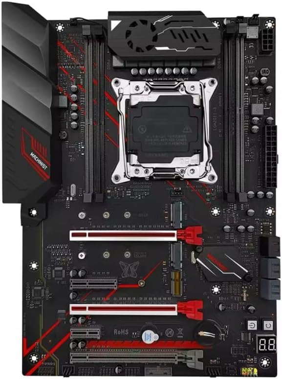
الشكل 2.2.2: من أعلى إلى أسفل view of the Machinist MR9A PRO MAX X99 Motherboard, showcasing its overall design and component placement.
2.3 الأبعاد

Figure 2.3.1: Dimensions of the Machinist MR9A PRO MAX X99 Motherboard, measuring approximately 300mm in length and 215mm in width.
2.4 الملحقات المضمنة

Figure 2.4.1: Standard accessories included with the motherboard, typically a CPU fan bracket with screws and a SATA data cable.
3. المواصفات
| ميزة | مواصفة |
|---|---|
| الشركة المصنعة | ميكانيكي |
| رقم الموديل | ERY-100 |
| مقبس وحدة المعالجة المركزية | LGA 2011-3 (Note: Product page lists LGA 1700, but title/description confirm LGA 2011-3 for Xeon E5 V3&V4) |
| المعالجات المتوافقة | Intel Xeon E5 V3&V4 Series |
| تقنية ذاكرة الوصول العشوائي (RAM) | دي دي ار 4 |
| الحد الأقصى لحجم ذاكرة الوصول العشوائي (RAM) | 64 جيجا بايت |
| فتحات الذاكرة المتاحة | 4 (Four Channel) |
| نوع الشريحة | X99 (Note: Product page lists Intel B760, but title/description confirm X99) |
| واجهة التخزين | SATA, NVME M.2 |
| منافذ USB | يو إس بي 3.0، يو إس بي 2.0 |
4. تعليمات الإعداد
4.1 قبل أن تبدأ
- Ensure you have all necessary components: CPU, CPU cooler, RAM, storage devices (SSD/HDD), power supply, and a compatible PC case.
- Work on a clean, flat, and static-free surface. Use an anti-static wrist strap or frequently touch a grounded metal object to discharge static electricity.
- راجع دليل تركيب علبة الكمبيوتر الخاص بك للحصول على تعليمات التركيب المحددة.
4.2 تركيب اللوحة الأم
- إعداد القضية: Install the I/O shield into the rear opening of your PC case. Install standoffs in the case according to the motherboard's mounting holes.
- تثبيت وحدة المعالجة المركزية: Open the CPU socket retention lever. Carefully align the CPU with the socket, ensuring the golden triangle on the CPU matches the triangle on the socket. Gently place the CPU into the socket without forcing it. Close the retention lever to secure the CPU.
- تثبيت مبرد وحدة المعالجة المركزية: Apply thermal paste to the CPU if not pre-applied on the cooler. Mount the CPU cooler according to its instructions, ensuring it is securely fastened and makes good contact with the CPU. Connect the CPU fan cable to the 'CPU_FAN' header on the motherboard.
- تثبيت RAM: Open the clips on the DDR4 memory slots. Align the RAM module with the slot, ensuring the notch on the module matches the key in the slot. Press down firmly on both ends of the module until the clips snap into place. For optimal performance, install RAM in the recommended dual-channel or quad-channel configuration as per the motherboard's silkscreen or manual.
- تثبيت أجهزة التخزين:
- M.2 SSD: Insert the M.2 SSD into the appropriate M.2 slot (NVME M.2 or SATA M.2) at an angle, then gently push it down and secure it with the provided screw.
- محركات SATA: Connect SATA data cables from your SSDs/HDDs to the SATA ports on the motherboard.
- تركيب اللوحة الأم: ضع اللوحة الأم بعناية في صندوق الكمبيوتر، مع محاذاة فتحات البراغي مع قواعد التثبيت المثبتة. ثبت اللوحة الأم بالبراغي.
- توصيل التيار الكهربائي: Connect the 24-pin ATX power cable from your power supply to the main 24-pin power connector on the motherboard. Connect the 8-pin (or 4+4-pin) CPU power cable to the 8-pin CPU power connector. Connect SATA power cables to your storage drives.
- توصيل كابلات اللوحة الأمامية: Connect the power button, reset button, HDD LED, power LED, and USB/audio headers from your PC case to the corresponding pins on the motherboard's front panel header. Refer to the motherboard layout diagram (Figure 2.2.1) for pin locations.
- تثبيت بطاقات التوسعة: Insert graphics cards or other PCIe expansion cards into the appropriate PCIe slots and secure them with the case's retention mechanism.
5. تشغيل اللوحة الأم
5.1 First Boot and BIOS/UEFI Setup
After completing the hardware installation, connect your monitor, keyboard, and mouse. Power on your system.
- أثناء عملية بدء التشغيل، اضغط بشكل متكرر على ديل or F2 key (or as indicated on screen) to enter the BIOS/UEFI setup utility.
- In the BIOS/UEFI, you can configure boot order, system time, fan speeds, and other hardware settings. Ensure your storage drive is recognized and set as the primary boot device for OS installation.
- احفظ التغييرات واخرج من BIOS/UEFI. سيُعاد تشغيل النظام.
5.2 تثبيت نظام التشغيل وبرامج التشغيل
- قم بإدخال وسائط تثبيت نظام التشغيل (محرك أقراص USB أو DVD) واتبع التعليمات التي تظهر على الشاشة لتثبيت نظام التشغيل المفضل لديك.
- After OS installation, install the necessary drivers for your motherboard's components (chipset, LAN, audio, USB, etc.). These drivers are typically available on the manufacturer's website or included on a driver CD/USB drive with the motherboard.
- Regularly check the Machinist official website for the latest driver updates and BIOS/UEFI versions to ensure system stability and performance.
6. الصيانة
Proper maintenance can extend the lifespan of your motherboard and ensure stable operation.
- إزالة الغبار: نظّف الغبار من اللوحة الأم ومكوناتها دوريًا باستخدام الهواء المضغوط. تأكد من فصل النظام عن الكهرباء قبل التنظيف.
- تحديثات BIOS/UEFI: Update your BIOS/UEFI only when necessary, following the manufacturer's instructions carefully. Incorrect updates can damage the motherboard.
- تحديثات برنامج التشغيل: حافظ على تحديث برامج التشغيل الخاصة بك لضمان التوافق والأداء الأمثل مع البرامج والأجهزة الجديدة.
- إدارة الكابلات: Ensure cables inside the case are neatly routed to improve airflow and prevent obstruction.
7. استكشاف الأخطاء وإصلاحها
يوفر هذا القسم حلولاً للمشكلات الشائعة التي قد تواجهها.
| مشكلة | السبب المحتمل | حل |
|---|---|---|
| لا يتم تشغيل النظام. | Loose power cables, faulty power supply, incorrect front panel connections. | Check 24-pin and 8-pin power connections. Ensure power supply switch is ON. Verify front panel power button connection. Test with a known good power supply if possible. |
| لا يوجد عرض على الشاشة. | Graphics card not seated properly, monitor cable loose, faulty RAM. | Reseat graphics card. Check monitor cable connections. Try reseating RAM modules or testing with one module at a time. |
| System powers on but no POST (Power-On Self-Test). | CPU not seated correctly, RAM issues, short circuit. | Reseat CPU and check for bent pins. Reseat RAM. Remove all non-essential components and test. Check for any loose screws or components touching the motherboard. |
| لم يتم الكشف عن نظام التشغيل. | Incorrect boot order, faulty storage drive, loose SATA/M.2 cable. | Check BIOS/UEFI boot order. Ensure storage drive is properly connected. Test storage drive on another system if possible. |
| يتعطل النظام أو يتجمد. | Overheating, unstable overclock, faulty RAM, outdated drivers. | Monitor temperatures. Reset BIOS/UEFI to default settings. Run memory diagnostic tests. Update drivers. |
8. الضمان والدعم
For specific warranty information regarding your Machinist MR9A PRO MAX X99 Motherboard, please refer to the warranty card included with your product or visit the official Machinist webقد تختلف شروط وأحكام الضمان حسب المنطقة والتاجر.
For technical support, driver downloads, and BIOS/UEFI updates, please visit the official Machinist support webيمكنك أيضًا التواصل مع بائع التجزئة الخاص بك للحصول على المساعدة.


