
1. المقدمة
The diymore LCR-TC1 is a versatile multi-function transistor tester designed for automatic detection and measurement of various electronic components. This device can identify NPN and PNP transistors, N-channel and P-channel MOSFETs, diodes (including double diodes), thyristors, resistors, capacitors, and inductors. It features a full-color display for clear readings and is powered by a built-in lithium battery for convenience. This manual provides detailed instructions for the safe and effective use of your LCR-TC1 tester.
2. معلومات السلامة
- Always ensure the component under test is fully discharged before connecting it to the tester, especially capacitors. Failure to do so can damage the tester.
- حجم مدخلات الشحنtage is 4.5V. Do not use an over-voltage charger, as this will damage the tester's internal circuitry.
- Do not attempt to test components while they are connected to a live circuit.
- احتفظ بالجهاز بعيدًا عن الماء ودرجات الحرارة العالية.
- لا تفتح الصندوقasing of the device unless you are a qualified technician.
3. انتهى المنتجview
The diymore LCR-TC1 Multi-Function Tester is equipped with a clear display and intuitive controls for easy operation. Below is an illustration of the main components and their functions.

الشكل 3.1: LCR-TC1 Tester with labeled parts including 160x128 TFT display, IR receiver window, multi-function key, Start button, transistor test area, Zener diode test area, Micro USB charging interface, and charge indicator LED.
- 160x128 TFT Display: Shows test results and device status.
- نافذة مستقبل الأشعة تحت الحمراء: Used for decoding Hitachi-style IR remote control signals.
- مفتاح متعدد الوظائف: For navigating menus or selecting options (if applicable).
- زر البدء: Initiates the component test.
- Transistor Test Area: ZIF (Zero Insertion Force) socket for connecting components with multiple pins (e.g., transistors, ICs). Numbered pins (1, 2, 3) correspond to test points.
- Zener Diode Test Area: Dedicated area for testing Zener diodes.
- Micro USB Charging Interface: لشحن بطارية الليثيوم الداخلية.
- مؤشر الشحن LED: يضيء باللون الأخضر عندما تكون البطارية مشحونة بالكامل.
4. المواصفات
The following table outlines the key performance parameters and general specifications of the diymore LCR-TC1 Multi-Function Transistor Tester.
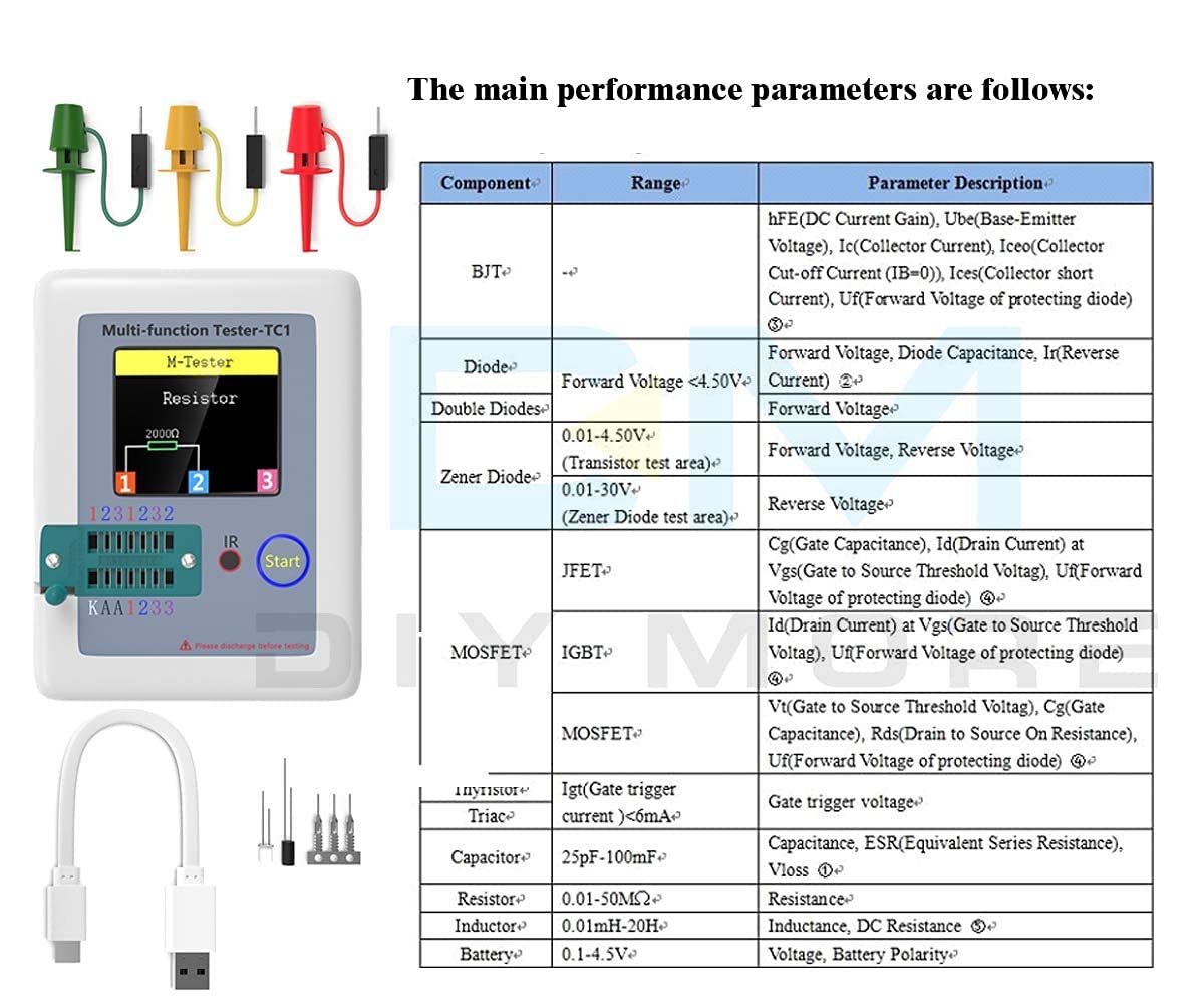
الشكل 4.1: Main performance parameters including component types (BJT, Diode, Double Diodes, Zener Diode, JFET, MOSFET, IGBT, Thyristor/Triac, Capacitor, Resistor, Inductor, Battery) and their respective measurement ranges and parameter descriptions.
| المعلمة | قيمة |
|---|---|
| ماركة | دييمور |
| رقم الموديل | LCR-TC1 |
| مصدر الطاقة | يعمل بالبطارية (بطارية ليثيوم مدمجة) |
| الحد الأدنى لحجم التشغيلtage | 4.5 Volts (Charging Input) |
| الحد الأقصى لحجم التشغيلtage | 4.5 Volts (Charging Input) |
| نوع القياس | مقياس LCR |
| وزن العنصر | 0.12 كيلوغرام |
| بلد المنشأ | الصين |
| المكونات المضمنة | Transistor Meter |
5. الإعداد
Before using your LCR-TC1 tester for the first time, ensure it is adequately charged.
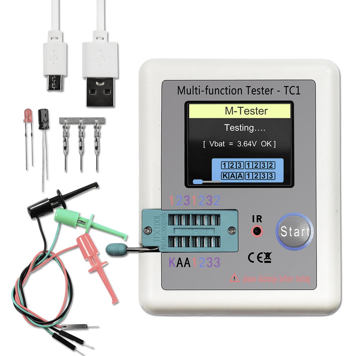
الشكل 5.1: LCR-TC1 tester shown with a Micro USB charging cable and various test clips, indicating readiness for use or charging.
- شحن البطارية: Connect the provided Micro USB cable to the charging interface on the tester and to a 4.5V USB power adapter (not included). The charge indicator LED will show the charging status. It will turn green when fully charged. Avoid using chargers with voltagتتجاوز 4.5 فولت.
- التشغيل الأولي: Press the "Start" button to power on the device. The display will light up, and the tester will perform a self-check.
- توصيل أسلاك الاختبار: For components that cannot be inserted directly into the ZIF socket, use the included test clips. Connect the clips to the corresponding test points (1, 2, 3) on the tester.
6. تعليمات التشغيل
The LCR-TC1 tester is designed for automatic component identification and measurement. Follow these steps for testing various components.
6.1. General Testing Procedure
- Ensure the component to be tested is discharged, especially capacitors.
- Connect the component to the tester. You can use the ZIF socket for multi-pin components or the test clips for others. Ensure good contact between the component leads and the test points (1, 2, or 3).
- Press the "Start" button. The tester will automatically identify the component type and measure its parameters.
- The results will be displayed on the TFT screen.
- The device has an automatic shutdown function to conserve battery. It will power off after approximately 20 seconds of inactivity.
6.2. Testing Specific Components

الشكل 6.1: Visual representation of the LCR-TC1 tester's capability to measure Inductance, Capacitance, Diode characteristics, and Resistance, showing typical component connections.
- المقاومات: Connect the resistor leads to any two of the test points (1, 2, or 3). The tester will display the resistance value.
- المكثفات: Connect the capacitor leads to any two of the test points (1, 2, or 3). Ensure the capacitor is discharged before testing. The tester will display capacitance, ESR (Equivalent Series Resistance), and Vloss.
- المحاثات: Connect the inductor leads to any two of the test points (1, 2, or 3). The tester will display the inductance value and DC resistance.
- Diodes (including Double Diodes): Connect the diode leads to any two test points. The tester will identify the diode type and display forward voltage and reverse current.
- Transistors (NPN, PNP, MOSFET, JFET, IGBT): Insert the transistor leads into the ZIF socket, ensuring each lead (Emitter, Base, Collector for BJT; Source, Gate, Drain for FET) connects to a different test point (1, 2, or 3). The tester will identify the type, pinout, and measure parameters like hFE, Ube, Vt, Cgs, etc.

الشكل 6.2: A MOSFET connected to the LCR-TC1 tester using test clips, demonstrating how to test multi-pin components that may not fit the ZIF socket directly.
- Thyristors and Triacs: Connect the leads to test points. The tester will identify the component and its gate trigger current.
- ثنائيات زينر: Use the dedicated Zener diode test area for accurate measurements of Zener voltage.
- IR Remote Control Signals: Point a Hitachi-style IR remote control towards the IR receiver window and press a button. The tester will attempt to decode and display the signal.
7. الصيانة
- تنظيف: Use a soft, dry cloth to clean the exterior of the tester. Do not use abrasive cleaners or solvents.
- تخزين: قم بتخزين الجهاز في مكان بارد وجاف بعيدًا عن أشعة الشمس المباشرة ودرجات الحرارة القصوى.
- العناية بالبطارية: اشحن البطارية بانتظام، حتى لو لم يكن الجهاز قيد الاستخدام المتكرر، للحفاظ على صحة البطارية. تجنب تفريغ البطارية بالكامل لفترات طويلة.
8. استكشاف الأخطاء وإصلاحها
| مشكلة | السبب المحتمل | حل |
|---|---|---|
| الجهاز لا يعمل. | بطارية منخفضة أو فارغة. | Charge the device using a 4.5V Micro USB charger. |
| Incorrect or no reading displayed. | Poor connection to component; Component not discharged; Component is faulty. | Ensure component leads are clean and securely connected. Discharge capacitors before testing. Test a known good component to verify tester functionality. |
| Tester shuts off too quickly. | Automatic shutdown feature activated. | This is normal behavior to save battery. Press "Start" to reactivate. |
| البطارية لا تحتفظ بالشحن. | Aging battery; Incorrect charging voltage. | Ensure you are using a 4.5V charger. If the issue persists, the internal battery may need replacement by a qualified technician. |
9. الدعم والضمان
For any questions, technical assistance, or if you require further support regarding your diymore LCR-TC1 Multi-Function Transistor Tester, please contact the manufacturer or seller via email. Refer to your purchase documentation for specific contact details.
Regarding warranty, the product typically comes with a 10-day replacement policy. Please consult your retailer or purchase platform for the most accurate and up-to-date warranty information and terms of service.