
1. انتهى المنتجview
The LCLCTC LC108 is an intelligent PID temperature controller designed for precise temperature regulation in various industrial and scientific applications. It features a clear LCD display, supports multiple thermocouple (TC) and RTD inputs, and provides SSR output for control. Equipped with RS-485 Modbus-RTU communication, it allows for integration into larger control systems. This manual provides essential information for the safe and effective installation, operation, and maintenance of your LC108 temperature controller.

Figure 1: LCLCTC LC108 PID Temperature Controller, Solid State Relay (SSR), and K-Type Thermocouple Sensor.
2. الميزات الرئيسية
- مزود الطاقة: Operates on 85~265VAC, 50~60Hz.
- حجم اللوحة: Compact 48x48mm design for easy integration.
- أنواع المدخلات: Supports various Thermocouple (K, J, E, T, S) and RTD (PT100, Cu100, Cu50) inputs, selectable via menu.
- الإخراج: SSR (Solid State Relay) output for precise control.
- الانذارات: Features up to 2 configurable alarms.
- تواصل: Integrated RS-485 Modbus-RTU for data exchange and remote control.
- دقة: High precision with 0.2% F.S. (Full Scale) accuracy.
- Sampوقت لينغ: Fast 0.5 second sampمعدل لينغ.
- بيئة: Designed for operation in 0-50℃ with humidity less than 85% (non-condensing).

Figure 2: The LC108 controller supports RS485 communication, making it compatible with various upstream equipment for integrated control systems.
3. محتويات العبوة
تأكد من أن جميع العناصر موجودة وغير تالفة عند فتح العبوة:
- 1 x LCLCTC LC108 PID Temperature Controller
- 1 x SSR 40DA Solid State Relay
- 1 x K-Type Thermocouple Sensor
- 1 × دليل التعليمات (هذه الوثيقة)
4. المواصفات
| يصف | قيمة |
|---|---|
| نوع العرض | شاشة الكريستال السائل |
| درجة حرارة التشغيل | 0-50 درجة مئوية |
| رمز المنتج الموحد | 735373853112 |
| الشركة المصنعة | LCLCTC |
| Product Dimensions (Controller) | 1.89 بوصة طول × 1.89 بوصة عرض × 1.89 بوصة ارتفاع (48 × 48 × 48 مم) |
| وزن العنصر (وحدة التحكم) | 5.75 أونصة (163 جم) |
| ASIN | B0CCKQPQCS |
| بلد المنشأ | الصين |
| المجلدtage | 85-265 Volts AC |
| لون | رمادي |
| المكونات المضمنة | Controller, SSR, Sensor |
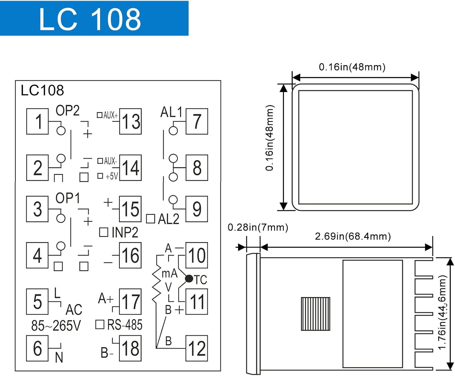
Figure 3: LC108 Controller Dimensions and Basic Pinout Diagram.

Figure 4: Dimensions and Specifications for the Solid State Relay (SSR) and K-Type Thermocouple Probe.
5. الإعداد والتثبيت
السلامة أولاً: Ensure all power is disconnected before attempting any wiring or installation. Improper wiring can lead to electric shock or damage to the device.
5.1 تركيب وحدة التحكم
The LC108 controller is designed for panel mounting. Cut a square opening of 45x45mm (1.77x1.77 inches) in your control panel. Insert the controller from the front and secure it using the provided mounting brackets from the rear.
5.2 مخطط الأسلاك
Refer to the wiring diagram below for connecting the power supply, sensor, SSR, and alarm outputs. Ensure correct polarity and secure connections for reliable operation.
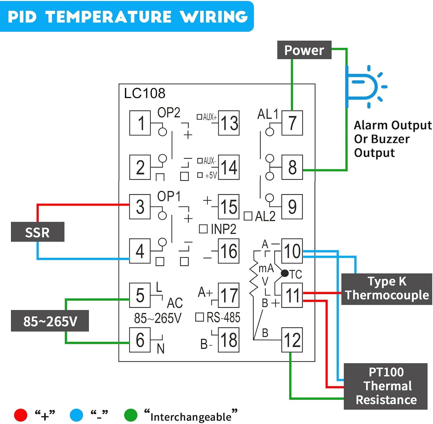
Figure 5: Detailed PID Temperature Controller Wiring Diagram. Connect power to terminals 5 and 6 (85-265V AC). Connect the SSR to terminals 3 and 4. Connect the Type K Thermocouple to terminals 10 and 11. PT100 Thermal Resistance connects to terminals 10, 11, and 12. Alarm output connects to terminals 7 and 8.
- مدخل الطاقة (تيار متردد 85-265 فولت): Connect to terminals 5 (L) and 6 (N).
- مخرجات SSR: Connect the control terminals of the Solid State Relay to terminals 3 (OP1+) and 4 (OP1-).
- Thermocouple/RTD Input:
- For K-Type Thermocouple: Connect to terminals 10 (TC+) and 11 (TC-).
- For PT100 RTD: Connect to terminals 10, 11, and 12 (refer to diagram for specific connections).
- ناقوس الخطر الناتج: Connect alarm devices (e.g., buzzer, indicator light) to terminals 7 (AL1) and 8 (AL1).
- اتصالات RS-485: Connect A+ to terminal 17 and B- to terminal 18 for Modbus communication.
6. تعليمات التشغيل
6.1 التشغيل والعرض الأولي
Once wired correctly, apply power. The controller will perform a self-test and then display the Process Value (PV) and Set Value (SV) on the LCD. PV indicates the current measured temperature, and SV is the desired temperature setpoint.
6.2 Setting the Temperature Setpoint (SV)
- اضغط على تعيين button briefly. The SV display will start flashing.
- استخدم ▲ (أعلى و ▼ (down) arrow buttons to adjust the SV to your desired temperature.
- يضعط تعيين again to confirm the new setpoint. The SV display will stop flashing.
6.3 تكوين المعلمة
The LC108 has various parameters for advanced configuration (e.g., input type, control mode, alarm settings, PID parameters). To access these:
- اضغط مع الاستمرار على تعيين button for approximately 3-5 seconds to enter the parameter setting menu.
- استخدم تعيين button to cycle through different parameters.
- استخدم ▲ و ▼ buttons to change the value of the selected parameter.
- اضغط مع الاستمرار تعيين again to save changes and exit the parameter menu, or wait for the controller to automatically exit after a period of inactivity.
Note: Refer to the detailed parameter list in the full technical manual (if available) for specific parameter codes and their functions. Incorrect parameter settings can lead to improper operation.
7. الصيانة
The LC108 PID Temperature Controller is designed for long-term, reliable operation with minimal maintenance. However, periodic checks can ensure optimal performance:
- تنظيف: امسح الشاشة واللوحة برفق بقطعة قماش ناعمة وجافة. لا تستخدم المنظفات الكاشطة أو المذيبات.
- الاتصالات: Periodically check all wiring connections to ensure they are secure and free from corrosion. Loose connections can cause erratic readings or control issues.
- بيئة: Ensure the operating environment remains within specified temperature and humidity ranges to prevent damage to internal components. Avoid excessive dust or moisture.
- فحص المستشعر: If temperature readings become inaccurate, inspect the thermocouple or RTD sensor for physical damage or degradation.
8. استكشاف الأخطاء وإصلاحها
| مشكلة | السبب المحتمل | حل |
|---|---|---|
| وحدة التحكم لا تعمل بالطاقة. | لا يوجد مصدر للطاقة، الأسلاك غير صحيحة. | Check power connections (terminals 5 & 6) and ensure voltage is within 85-265VAC. Verify power source is active. |
| Inaccurate temperature reading (PV). | Incorrect sensor type selected; faulty sensor; loose sensor connection. | Verify the input type setting matches your sensor (K, PT100, etc.). Check sensor wiring to terminals 10, 11, 12. Replace sensor if damaged. |
| Output (SSR) not activating. | Incorrect control mode; SV not set correctly; faulty SSR; incorrect SSR wiring. | Check control mode settings. Ensure SV is set appropriately. Verify SSR wiring to terminals 3 & 4. Test SSR functionality. Note: Some SSRs require an external power supply for their control circuit if the controller's output is insufficient. |
| RS-485 communication issues. | Incorrect wiring (A+/B-); wrong communication parameters (baud rate, parity); address conflict. | Verify A+ and B- connections to terminals 17 & 18. Check communication settings in the controller and master device. Ensure unique Modbus addresses. |
| Controller displays "HHHH" or "LLLL". | Sensor open circuit (HHHH) or short circuit (LLLL) / out of range. | Check sensor wiring for breaks or shorts. Ensure sensor is within its specified temperature range. Replace sensor if necessary. |
9. الضمان والدعم
LCLCTC products are manufactured to high quality standards. For warranty information, technical support, or service inquiries, please contact your original point of purchase or the manufacturer directly through their official website. Please have your product model number (LC108) and purchase details ready when contacting support.
For further assistance, you may refer to the manufacturer's online resources or contact their customer service department.