
Mollom G75-220V
MOLLOM VFD 220V 5.5KW 7.5HP Variable Frequency Drive User Manual
Model: G75-220V
1. المقدمة
This manual provides essential information for the safe and efficient operation of your MOLLOM 220V 5.5KW 7.5HP Variable Frequency Drive (VFD). Please read this manual thoroughly before installation, operation, or maintenance to ensure proper usage and prevent potential hazards.
The MOLLOM VFD is designed to control the speed of three-phase AC motors, offering precise control for various applications such as CNC routers, milling machines, and pumps. It supports both single-phase and three-phase 220V input.
2. احتياطات السلامة
يرجى دائمًا مراعاة احتياطات السلامة التالية لمنع الإصابة الشخصية أو تلف المعدات.
- المخاطر الكهربائية: Ensure power is disconnected before wiring or performing maintenance. Only qualified personnel should perform electrical work.
- التأريض: يجب تأريض محول التردد المتغير بشكل صحيح لمنع حدوث صدمة كهربائية.
- اتصال المحرك: The frequency converter must be directly connected to the motor. Control motor start/stop exclusively through the VFD to avoid damage.
- بيئة: Avoid operating the VFD in humid environments, or where water mist, water droplets, or metal objects may fall into the unit, as this can cause short circuits.
- External Resistor: If your motor operates under heavy load, consider using an external braking resistor.
3. المواصفات
| ميزة | مواصفة |
|---|---|
| قوة | 5.5KW (7.5HP) |
| حجم الإدخالtage | تيار متردد 220 فولت (±15%) |
| حجم الإخراجtage | تيار متردد 220 فولت |
| الحد الأقصى لتيار الإخراج | 25 أمبير |
| تردد الإدخال | 50/60 هرتز |
| تردد الإخراج | 0-3000 هرتز |
| مرحلة الإدخال | Single or Three Phase |
| مرحلة الإخراج | ثلاث مراحل |
| الأبعاد (الطول × العرض × الارتفاع) | 5.9 × 7.3 × 10.2 بوصة (150 × 185 × 260 مم) |
| رقم الموديل | G75-220 فولت |
| نوع العرض | رقمي |
| مادة | أكريلونيتريل بوتادين ستايرين (ABS) |
4. مكونات المنتج وأبعاده
The MOLLOM VFD unit includes the main inverter and a detachable control panel. Below are images illustrating the unit's appearance and dimensions.

الشكل 4.1: أمام view of the MOLLOM VFD 5.5KW 7.5HP unit. This image shows the main body of the Variable Frequency Drive with its control panel integrated, displaying the brand logo and warning symbols.

الشكل 4.2: Dimensions of the MOLLOM VFD. This image provides a side view of the VFD unit with measurements indicating its length (10.2 inches), width (7.3 inches), and depth (5.9 inches).

الشكل 4.3: مفصل view of the VFD control panel. This image highlights the various buttons and indicators on the control panel, including the State LED, Unit LED, Code Display, UP/DOWN buttons, Potentiometer, PRG (Programming/Return), ENTER, SHIFT-Right, RUN, MF.K (Function/Jog), and STOP/RST (Stop/Reset) buttons.

الشكل 4.4: MOLLOM VFD with its detachable control panel. This image shows the main VFD unit alongside its separated control panel, illustrating the remote control capability.
5. الإعداد والأسلاك
Proper wiring is crucial for the safe and correct operation of the VFD. Refer to the wiring diagram below and follow these instructions carefully.

الشكل 5.1: Wiring diagram for connecting the VFD to a motor. This diagram illustrates the connections for single or three-phase 220V input (R, S, T terminals), grounding (PE terminal), three-phase 220V output to the motor (U, V, W terminals), and optional braking resistor connections (P+, BR terminals).
5.1 توصيل طاقة الإدخال
- Connect the AC 220V input power to the terminals labeled R, S، و T.
- For single-phase 220V input, connect the live wire to R and the neutral wire to T (أو L و N if labeled differently).
- For three-phase 220V input, connect each phase to R, S، و T على التوالى.
- Ensure proper circuit breakers are installed upstream for protection.
5.2 اتصال المحرك
- Connect the three-phase motor wires to the VFD output terminals labeled U, V، و W.
- Refer to your motor's wiring diagram to ensure it is configured for 220V operation (typically Delta connection for 220V).
- If the motor rotates in the wrong direction, you can swap any two of the U, V, W output wires, or adjust the rotation direction in the VFD's parameters.
- مهم: The motor must be directly connected to the VFD. Do not place any switches or contactors between the VFD and the motor.
5.3 التأريض
- Connect the ground wire from your power supply and the motor frame to the VFD's PE (Protective Earth) terminal.
- Ensure a solid, low-impedance ground connection.
5.4 Braking Resistor (Optional)
- For applications requiring rapid deceleration or operating with high inertia loads, an external braking resistor can be connected to terminals P+ و BR.
- Consult the VFD specifications and your application requirements to select an appropriate braking resistor.
6. التشغيل
This section covers basic operation and parameter settings for the MOLLOM VFD.
6.1 وظائف لوحة التحكم
- PRG (Programming/Return): Enters/exits parameter setting mode, or returns to the previous menu.
- أدخل: Confirms parameter changes or enters sub-menus.
- الأسهم لأعلى/لأسفل: تصفح المعلمات أو اضبط القيم.
- SHIFT-Right: Shifts the cursor during parameter value entry.
- RUN: يبدأ المحرك.
- STOP/RST: يوقف المحرك أو يعيد ضبط حالات الأعطال.
- MF.K (Function/Jog): Activates special functions or jog mode.
- مقياس الجهد: Adjusts the output frequency (speed) in manual mode.
6.2 Basic Parameter Setting
The VFD comes with default settings. You may need to adjust certain parameters for your specific motor and application. Common parameters include:
- ص0.03: Control mode selection (e.g., V/F control, vector control).
- ص0.04: Maximum output frequency (e.g., 60Hz for standard motors).
- ص0.10: Accelerating time.
- ص0.11: Decelerating time.
- ف0.02: إعادة ضبط المصنع.
For detailed parameter descriptions and advanced settings, refer to the comprehensive user manual PDF available for download or contact technical support.

الشكل 6.1: Example of VFD parameter settings for spindle control. This image displays a table of various parameters (e.g., P0.03, P0.04, P0.10, F0.02) with their setting ranges and instructions, useful for configuring the VFD for specific applications like CNC spindle motors.
6.3 Starting and Stopping the Motor
- يبدأ: اضغط على يجري الزر الموجود على لوحة التحكم.
- توقف: اضغط على STOP/RST الزر الموجود على لوحة التحكم.
- Adjust motor speed using the potentiometer or programmed external controls.
7. الصيانة
تضمن الصيانة الدورية طول عمر جهاز VFD الخاص بك وتشغيله الموثوق.
- تنظيف: حافظ على نظافة محول التردد المتغير وخلوه من الغبار والأوساخ. استخدم قطعة قماش ناعمة وجافة للتنظيف. لا تستخدم المنظفات السائلة.
- تهوية: Ensure adequate airflow around the VFD. Regularly check that cooling fans and vents are not obstructed.
- الاتصالات: Periodically check all electrical connections for tightness. Loose connections can cause overheating or intermittent operation.
- الفحص البيئي: تأكد من أن بيئة التشغيل تظل ضمن نطاقات درجة الحرارة والرطوبة المحددة.
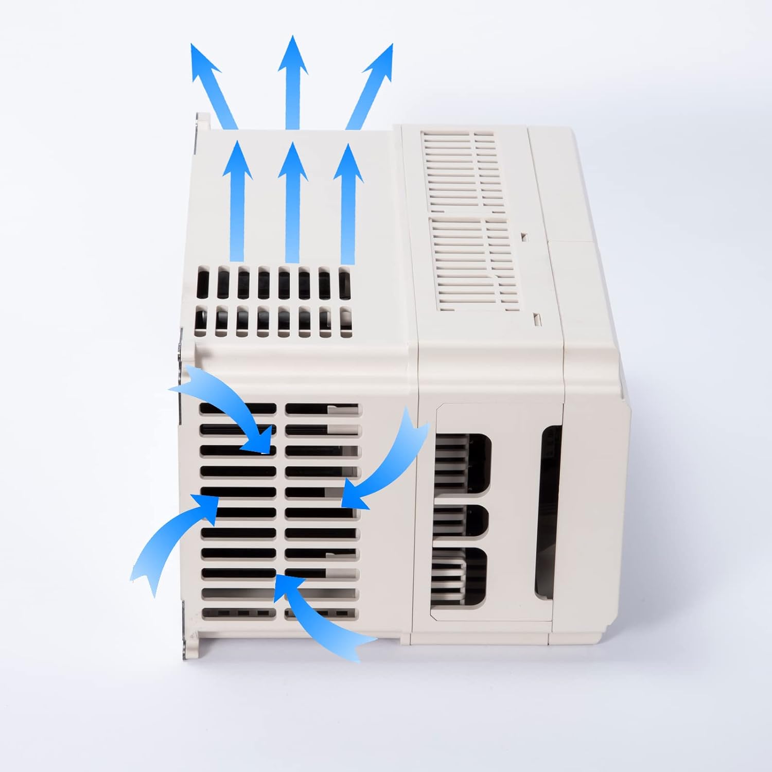
الشكل 7.1: Illustration of the VFD's cooling airflow. This image shows blue arrows indicating the path of air entering through the side vents and exiting through the top, demonstrating the cooling mechanism of the unit.
8. استكشاف الأخطاء وإصلاحها
يقدم هذا القسم إرشادات حول المشكلات الشائعة. في حال وجود مشكلات معقدة، يُرجى التواصل مع الدعم الفني.
| مشكلة | السبب المحتمل | حل |
|---|---|---|
| لا يعمل محول التردد المتغير | No input power; Blown fuse/breaker; Incorrect wiring | Check power supply; Inspect fuses/breakers; Verify input wiring (R, S, T). |
| المحرك لا يبدأ | Incorrect parameters; Emergency stop active; Motor wiring error | Check motor parameters (e.g., frequency, voltage); Ensure no emergency stop is engaged; Verify motor connections (U, V, W). |
| المحرك يدور في الاتجاه المعاكس | Motor phase sequence incorrect | Swap any two of the U, V, W output wires, or change direction parameter in VFD settings. |
| عطل التيار الزائد/الحمل الزائد | زيادة حمل المحرك؛ ماس كهربائي؛ زمن التسارع قصير جدًا | قلل حمل المحرك؛ افحص المحرك والأسلاك بحثًا عن أي تماس كهربائي؛ زد قيمة معامل زمن التسارع. |
| أوفرفولtagخطأ | Deceleration time too short; High inertia load without braking resistor | Increase deceleration time; Install or check braking resistor. |
9. الدعم الفني والضمان
For further assistance with parameter settings, troubleshooting, or any other technical inquiries, please contact MOLLOM customer support.
When contacting support, please provide your VFD model number (G75-220V) and a detailed description of your issue, including any error codes displayed on the VFD.
دليل المستخدم الشامل بصيغة PDF متاح أيضًا للتنزيل: MOLLOM VFD User Manual (PDF).
معلومات الضمان: Please refer to the warranty card included with your product or contact MOLLOM customer service for details regarding warranty coverage and terms.

الشكل 9.1: Illustration representing technical support. This image shows a stylized figure interacting with a parameter setting screen, symbolizing the availability of assistance for VFD configuration.
Ask a question about this manual
Ask about setup, troubleshooting, compatibility, parts, safety, or missing instructions. Manuals+ will review the question and use this page’s manual context to help answer it.