
Zerone KG1204-A
Zerone KG1204-A 4-Channel 12V Wireless Remote Control System User Manual
Model: KG1204-A
1. المقدمة
This user manual provides comprehensive instructions for the Zerone KG1204-A 4-channel 12V wireless remote control system. This system is designed for various home and industrial automation applications, offering reliable wireless control over electrical appliances and equipment. Please read this manual thoroughly before installation and operation to ensure proper use and optimal performance.
2. انتهى المنتجview
The Zerone KG1204-A system includes a 4-channel receiver module and four remote control transmitters. The receiver operates on DC 12V and features high-capacity relays capable of handling loads up to 1000W (20A total load power). The remote controls operate at 433MHz, providing a wireless range of up to 100 meters in open, interference-free environments.

الشكل 2.1: Zerone KG1204-A receiver module and four remote control transmitters. The image displays the white plastic casing for the receiver, the green circuit board with four relays, and four black remote controls with metal keychains, each featuring four buttons.
محتويات الحزمة:
- 1 x KG1204-A Receiver Module
- 4 x Remote Control Transmitters
أشكال المنتج:
Please note that new and old models of the receiver board may be shipped randomly. While the core functionality remains the same, there might be minor visual differences in component layout or board design.

الشكل 2.2: Comparison of two versions of the KG1204-A receiver circuit board, labeled "New Type" and "Old Type". Both show similar components and terminal layouts, indicating functional equivalence despite minor design variations.
3. المواصفات
| ميزة | مواصفة |
|---|---|
| نموذج المنتج | KG1204-أ |
| العمل المجلدtage | تيار مستمر 12 فولت |
| التيار الساكن | 6 مللي أمبير |
| Total Load Current (Max) | 20 أمبير |
| Load Power (Max) | 1000 واط |
| تردد العمل | 433 ميجا هرتز |
| تلقي الحساسية | -105dbm |
| انحراف التردد | ± 0.2 ميجا هرتز |
| طريقة الترميز | كود التعلم |
| أوضاع العمل | Jog (Momentary), Self-lock (Toggle), Interlock (Latched) |
| طريقة التعديل | بسأل |
| مسافة التحكم عن بعد | Up to 100M (in open, interference-free areas) |
| حجم PCBA | الأبعاد التقريبية: 4.8 × 6.8 × 1.8 سم (1.9 × 2.7 × 0.7 بوصة) |
| حجم القشرة | الأبعاد التقريبية: 7.6 × 5.6 × 3 سم (3 × 2.2 × 1.2 بوصة) |
| وزن | تقريبا. 185 جم (0.41 رطل) |

الشكل 3.1: Close-up of the receiver circuit board, showing the four relays, terminal blocks for connections, the "Learn" button, and jumper pins for mode selection.
4. الإعداد والأسلاك
Proper wiring is essential for the safe and correct operation of the KG1204-A system. Ensure all power is disconnected before making any connections.
4.1 توصيل التيار الكهربائي
- Connect a DC 12V power supply to the receiver module's input terminals labeled أرضي (negative) and +V (إيجابي).
- Observe polarity to prevent damage to the module.
4.2 Output Wiring
The receiver provides four independent relay outputs, labeled A, B, C, and D. Each output has three terminals: مفتوح عادة (لا), مشترك (COM)، و مغلق عادة (NC). These outputs are passive, meaning they act as dry contacts and can be used to switch various devices, regardless of their voltage (within the relay's limits).
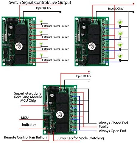
الشكل 4.1: Various wiring configurations for the receiver. The top left diagram shows a switch signal control, the top right shows live output control for multiple lights, and the bottom diagram illustrates the internal components and connection points for mode switching and pairing.
Example Wiring Configurations:
- Switch Signal Control: For applications where the relay acts as a simple switch (e.g., triggering a low-voltage input on another device), connect the device's control input to the COM and NO (or NC, depending on desired default state) terminals of a relay.
- Live Output Control: For controlling lights or other DC 12V devices directly, connect the positive lead of the external power source to the COM terminal and the device's positive lead to the NO terminal. The device's negative lead connects directly to the external power source's negative. Ensure the external power source matches the device's voltagالمتطلبات.
مهم: Always ensure the load's voltage and current ratings are within the relay's specifications (e.g., 20A, 1000W). Consult a qualified electrician if you are unsure about wiring connections or working with AC power.
5. أوضاع التشغيل
The KG1204-A receiver supports three primary working modes: Jog (Momentary), Self-lock (Toggle), and Interlock (Latched). These modes determine how the relay outputs behave when a remote control button is pressed. The mode is selected using jumper caps on the receiver board.

الشكل 5.1: The receiver board with jumpers indicating different modes: Inching (Jog), Interlocking, Self-locking, and Delay Locking. The image shows the receiver and four remote controls, with text labels for each mode.
5.1 Mode Selection via Jumpers
Locate the jumper pins on the receiver board. Typically, there are three pins for mode selection. The configuration of the jumper cap determines the operating mode. Refer to Figure 4.1 (bottom diagram) for the location of the "Jump Cap for Mode Switching".
- Jog (Momentary) Mode: The relay remains active only while the corresponding remote button is pressed. Release the button, and the relay deactivates. This mode is often used for temporary actions like opening a gate for a brief period.
(Specific jumper configuration for Jog mode: Typically, no jumper cap is installed, or a single jumper on specific pins.) - Self-lock (Toggle) Mode: Press the remote button once to activate the relay; press the same button again to deactivate it. This mode is suitable for on/off control of lights or other devices.
(Specific jumper configuration for Self-lock mode: Typically, a jumper cap connects two specific pins.) - Interlock (Latched) Mode: Pressing one button activates its corresponding relay and simultaneously deactivates all other active relays. Only one relay can be active at a time. This mode is useful for selecting between multiple outputs, such as controlling different directions of a motor.
(Specific jumper configuration for Interlock mode: Typically, a jumper cap connects a different set of two specific pins.)
حذر: Always disconnect power to the receiver before changing jumper settings to avoid damage or unintended operation.
6. Pairing Remote Controls (Learning Code)
The KG1204-A receiver uses a learning code method to pair with remote control transmitters. This allows you to add or replace remote controls. Each button on the remote can be paired to control a specific relay output.
6.1 إجراء الاقتران
- Ensure the receiver is powered on (DC 12V).
- Locate the "Learn" button on the receiver circuit board (refer to Figure 3.1 or 4.1 for its typical location near the indicator LED).
- Press and hold the "Learn" button for approximately 3 seconds. The indicator LED on the receiver will light up, indicating it is in learning mode.
- While the LED is lit, press any button on the remote control you wish to pair. The indicator LED on the receiver will flash once and then turn off, confirming successful pairing.
- To pair additional remote controls or different buttons on the same remote, repeat steps 3 and 4 for each desired button/remote.
6.2 Clearing Paired Remote Controls
To clear all paired remote controls from the receiver's memory:
- تأكد من تشغيل جهاز الاستقبال.
- Press and hold the "Learn" button for approximately 8 seconds. The indicator LED will light up, flash several times, and then turn off. This indicates that all stored remote control codes have been cleared.
- After clearing, you will need to re-pair any remote controls you wish to use, following the procedure in Section 6.1.
7. الصيانة
The Zerone KG1204-A system requires minimal maintenance. Follow these guidelines to ensure longevity and reliable operation:
- تنظيف: Use a dry, soft cloth to clean the receiver and remote controls. Avoid using liquid cleaners, solvents, or abrasive materials, as these can damage the components.
- بيئة: Install the receiver in a dry location, away from direct moisture, extreme temperatures, and direct sunlight. While the product is designed for general use, it is not specified as weatherproof and should be protected from outdoor elements.
- استبدال البطارية: Remote controls typically use small button-cell batteries (e.g., CR2032). If the remote's operating range decreases significantly or it stops responding, replace the battery. To replace, carefully open the remote control casing and insert a new battery, observing polarity.
8. استكشاف الأخطاء وإصلاحها
If you encounter issues with your Zerone KG1204-A system, refer to the following troubleshooting steps:
8.1 جهاز التحكم عن بعد لا يستجيب
- التحقق من الطاقة: Ensure the receiver is properly powered with a stable DC 12V supply. The indicator LED on the receiver should be off unless in learning mode or actively switching.
- البطارية عن بعد: استبدل البطارية في جهاز التحكم عن بعد.
- الاقتران: Verify that the remote control is correctly paired with the receiver. If unsure, clear all codes and re-pair the remote following the instructions in Section 6.
- Obstacles/Interference: Ensure there are no significant physical obstacles (e.g., thick walls, metal structures) between the remote and the receiver. Strong electromagnetic interference from other electronic devices can also affect performance.
- يتراوح: Confirm you are within the effective operating range (up to 100M in open areas). Walls and other structures will significantly reduce this range.
8.2 Relay Not Activating/Deactivating Correctly
- التوصيلات الكهربائية: Double-check all wiring connections to the relay outputs (COM, NO, NC) and the power supply. Ensure they are secure, correctly polarized, and match your intended application.
- حمولة: Verify that the connected load's voltage and current requirements do not exceed the maximum specified ratings of the relay (20A, 1000W). Overloading can prevent proper operation or damage the relays.
- وضع التشغيل: Confirm that the receiver is set to the desired operating mode (Jog, Self-lock, Interlock) using the jumpers (Section 5.1). An incorrect mode setting will result in unexpected relay behavior.
8.3 Unintended Activation (False Triggers)
In some environments, strong external radio frequency (RF) signals might cause unintended activation of the relays. This can be due to local interference sources.
- النقل: Try relocating the receiver to a different position, away from potential sources of strong RF interference (e.g., other wireless devices, vehicle keyless entry systems, high-power electrical equipment, or large metal objects).
- الحماية: If interference persists, consider placing the receiver in a non-metallic enclosure or a location that provides some RF shielding. Note that excessive shielding might reduce the remote control's effective range.
- إصلاح: Clearing all paired remotes and re-pairing them (Section 6.2 and 6.1) might help if a corrupted or conflicting code was inadvertently learned.
9. الضمان والدعم
Zerone products are manufactured to high-quality standards. For specific warranty information, please refer to the product packaging or contact your retailer. If you require technical assistance or have questions not covered in this manual, please contact Zerone customer support through their official channels or the retailer from whom you purchased the product.
لمزيد من المعلومات، يمكنك زيارة متجر زيرون على أمازون.
Ask a question about this manual
Ask about setup, troubleshooting, compatibility, parts, safety, or missing instructions. Manuals+ will review the question and use this page’s manual context to help answer it.